- 1. Welcome to Computer Vision
- 3. Overview
- 4. Getting Started
- 5. Distortion Correction
- 7. Pinhole Camera Model 针眼相机模式
- 9. Measuring Distortion
- 10. Finding Corners
- 11. 【重要:有详细的原理讲解】Calibrating Your Camera
- 12. Correcting for Distortion
- 13. Lane Curvature 车道曲率[跟高精度地图相关★重要]
- 14. Perspective Transform-透视变换
- 16. Transform a Stop Sign
- 17. Intuitions
- 18. Undistort and Transform
- 20. 总结:
1. Welcome to Computer Vision
Robotics can essentially be broken into a three step cycle.
- To sense or perceive the world.
- To decide what to do based on that perception.
- To perform an action to carry out that decision.
即感知,决策和执行三个步骤,computer vision is a major part of the perception step in that cycle.
80% of building a self-driving car is perception.
Later in the nano degree project, we will be using laser and radar data for the task of perception.

3. Overview
本章中要写一个更好的车道线定位算法,使得它可以处理弯曲的车道线,适应阴影和路面颜色的变化。
- 测量车道线的弯曲程度。
- 车辆与道路中心的相对位置。
在这之后,需要实现车辆检测与跟踪,在决定何时改变车道,何时加速,以及何时停止时,都需要知道其他车的位置。
本project分为两个部分:
- 车道线识别进阶
- 车辆检测与跟踪 最后把这两个项目结合起来,判断车辆在道路上的位置道路走向,以及视野中其他车的位置。
4. Getting Started
最终目标是测量控制汽车必需的一些数据,比如测量车道线的弯曲程度,需要:
- 在照片中定位出车道线的位置
- 然后通过透视变换,转换车道线视角
为了获得正确的视角,首先要纠正图像失真(比如图片的扭曲),摄像头无法拍摄出完美的图片,尤其是边缘的地方,可能会呈现不同程度的拉伸和倾斜,所以需要纠正。
5. Distortion Correction
Image Distortion: 将真实世界的三维图片转换成二维时的变形,这种转换并不是完美的。
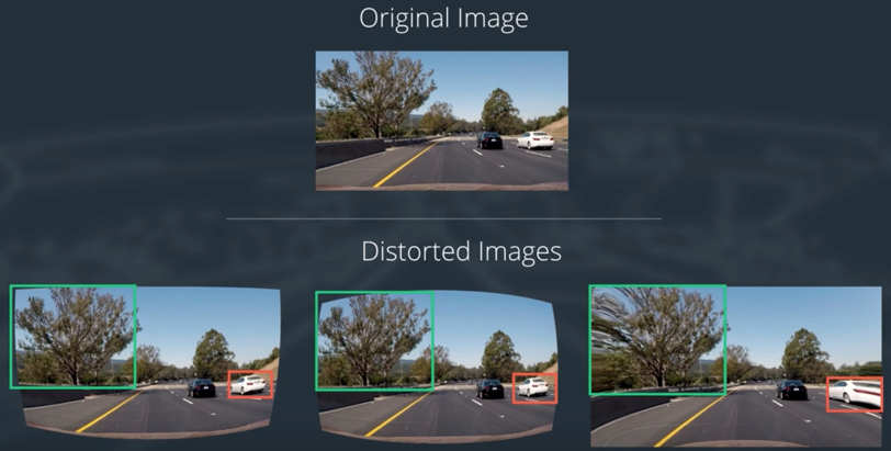
我们的最终目标是根据Lane的曲率去判断驾驶方向等,如果车道失真,我们就会得到错误的曲率,那么转向角度也会有问题。
所以处理图像的第一步工作,就是消除失真,这样才能从图像中获取有用的信息。
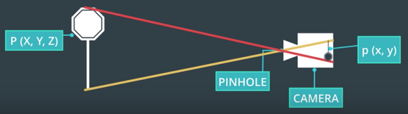
7. Pinhole Camera Model 针眼相机模式
7.1 Types of Distortion
- radial distortion 径向畸变 相机的镜头通常都是弧线的,光线通过弧线时会发生扭曲。 实际为直线的物体,会变得像曲线一样。 Real cameras use curved lenses to form an image, and light rays often bend a little too much or too little at the edges of these lenses. This creates an effect that distorts the edges of images, so that lines or objects appear more or less curved than they actually are。
实际物体,经过镜头的变换,会从3D转换到2D。 经过转换后,在镜头边缘的图像会发生变形,效果如下:

- tangential distortion 切向畸变 当镜头与摄像机胶片并不平行时,会导致物体看起来更远或是更近,距离不准确。 This occurs when a camera’s lens is not aligned perfectly parallel to the imaging plane, where the camera film or sensor is. This makes an image look tilted so that some objects appear farther away or closer than they actually are. 如鱼眼镜头或广角镜头,就是故意达到这种效果。
7.2 Distortion Coefficients and Correction 畸变系数和校正
通过调整后:

9. Measuring Distortion
10. Finding Corners
使用如下的两个函数,找到和画出棋盘的角落。
- cv2.findChessboardCorners() 查找
- cv2.drawChessboardCorners() 描绘
In the following exercise, your job is simple.
- Count the number of corners in any given row and enter that value in nx.
- Similarly, count the number of corners in a given column and store that in ny.
Keep in mind that “corners” are only points where two black and two white squares intersect, in other words, only count inside corners, not outside corners.
import numpy as np
import cv2
import matplotlib.pyplot as plt
import matplotlib.image as mpimg

# prepare object points
nx = 8#TODO: enter the number of inside corners in x
ny = 6#TODO: enter the number of inside corners in y

# Make a list of calibration images
fname = 'calibration_test.png'
img = cv2.imread(fname)

# Convert to grayscale
gray = cv2.cvtColor(img, cv2.COLOR_BGR2GRAY)

# Find the chessboard corners
ret, corners = cv2.findChessboardCorners(gray, (nx, ny), None)

# If found, draw corners
if ret == True:
    # Draw and display the corners
    cv2.drawChessboardCorners(img, (nx, ny), corners, ret)
    plt.imshow(img)
输出结果为:

11. 【重要:有详细的原理讲解】Calibrating Your Camera
-
读取图形
-
新建校正前坐标,与校正后坐标的数组,用于将畸变后的棋盘对应点,与真实没有畸变的棋盘图上的对应点进行一一对应。
-
将图像转换成灰度图,并使用
findChessboardCorners查找棋盘角点 -
将检测到的角点,添加到图像点的数组中
-
使用
drawChessboardCorners函数,描绘出棋盘角点 -
重复上述的步骤,处理其他的图形
下面讲解进行镜头校准和最终图像去畸变所涉及到的函数:
cv2.calibrateCamera(objpoints,imgpoints,gray.shape[::-1],None,None),通过输入原始图像的坐标,校正后图形坐标,形状信息,处理后其return为Return values:ret,mtx,dist,rvecs,tvecs,dist是失真系数,以及镜头在真实环境中的位置dst = cv2.undistort(img,mtx,dist,None,mtx),该函数接收一副畸变的图像镜头矩阵和失真系数,返回去除畸变后的图像,通常称为目标图形
11.1 参考代码
- 处理单幅图片
读取一副图片:
import numpy as np
import cv2
import matplotlib.pyplot as plt
import matplotlib.image as mpimg

%matplotlib inline

img = mpimg.imread('./calibration_wide/GOPR0032.jpg')
plt.imshow(img)
处理上面的图片:
objpoints = []
imgpoints = []

nx = 8
ny = 6

# 1. 生成8行6列的三维数组,[ 0.  0.  0.] [ 1.  0.  0.]
objp = np.zeros((ny*nx,3),np.float32)
objp[:,:2] = np.mgrid[0:nx,0:ny].T.reshape(-1,2)

# 2. 将图片转换为灰度图
gray = cv2.cvtColor(img,cv2.COLOR_BGR2GRAY)

# 3. 寻找棋盘的角落点
ret,corners = cv2.findChessboardCorners(gray,(nx,ny),None)

if ret == True:
    imgpoints.append(corners)
    objpoints.append(objp)

    # 4. 描画
    img = cv2.drawChessboardCorners(img, (nx, ny), corners, ret)
    plt.imshow(img)
最后单幅图显示如下:

- 处理复数的图片
获取一系列图片的路径:
import numpy as np
import cv2
import matplotlib.pyplot as plt
import matplotlib.image as mpimg
import glob

%matplotlib inline

images = glob.glob('./calibration_wide/GOPR00*.jpg')
处理一系列的图片:
objpoints = []
imgpoints = []

nx = 8#TODO: enter the number of inside corners in x
ny = 6#TODO: enter the number of inside corners in y

objp = np.zeros((ny*nx,3),np.float32)
objp[:,:2] = np.mgrid[0:nx,0:ny].T.reshape(-1,2)

for fname in images:
    img = mpimg.imread(fname)
    gray = cv2.cvtColor(img,cv2.COLOR_BGR2GRAY)

    ret,corners = cv2.findChessboardCorners(gray,(nx,ny),None)

    if ret == True:
        imgpoints.append(corners)
        objpoints.append(objp)

        img = cv2.drawChessboardCorners(img, (nx, ny), corners, ret)
        plt.imshow(img)
12. Correcting for Distortion
There are two main steps to this process:
- use chessboard images to obtain image points and object points ,先使用棋盘图像获取图像点和目标点
- and then use the OpenCV functions cv2.calibrateCamera() and cv2.undistort() to compute the calibration and undistortion,再使用OpenCV函数
cv2.calibrateCamera()和cv2.undistort()去计算校正参数
参考代码:
import pickle
import cv2
import numpy as np
import matplotlib.pyplot as plt
import matplotlib.image as mpimg

# Read in the saved objpoints and imgpoints
dist_pickle = pickle.load( open( "./12/wide_dist_pickle.p", "rb" ) )
objpoints = dist_pickle["objpoints"]
imgpoints = dist_pickle["imgpoints"]

# Read in an image
img = cv2.imread('./12/test_image.png')

# TODO: Write a function that takes an image, object points, and image points
# performs the camera calibration, image distortion correction and
# returns the undistorted image
def cal_undistort(img, objpoints, imgpoints):
    # Use cv2.calibrateCamera() and cv2.undistort()
    gray = cv2.cvtColor(img,cv2.COLOR_BGR2GRAY)
    ret, mtx, dist, rvecs, tvecs = cv2.calibrateCamera(objpoints, imgpoints, gray.shape[::-1], None, None)
    #undist = np.copy(img)  # Delete this line
    undist = cv2.undistort(img, mtx, dist, None, mtx)
    return undist

undistorted = cal_undistort(img, objpoints, imgpoints)

f, (ax1, ax2) = plt.subplots(1, 2, figsize=(24, 9))
f.tight_layout()
ax1.imshow(img)
ax1.set_title('Original Image', fontsize=50)
ax2.imshow(undistorted)
ax2.set_title('Undistorted Image', fontsize=50)
plt.subplots_adjust(left=0., right=1, top=0.9, bottom=0.)
下面这个函数是增加的,通过给定的原始坐标和校正坐标来校正图像:
def cal_undistort(img, objpoints, imgpoints):
    # Use cv2.calibrateCamera() and cv2.undistort()
    gray = cv2.cvtColor(img,cv2.COLOR_BGR2GRAY)
    ret, mtx, dist, rvecs, tvecs = cv2.calibrateCamera(objpoints, imgpoints, gray.shape[::-1], None, None)
    #undist = np.copy(img)  # Delete this line
    undist = cv2.undistort(img, mtx, dist, None, mtx)
    return undist
处理后的图像对比如下:

13. Lane Curvature 车道曲率[跟高精度地图相关★重要]
本节重要,需要自己去拓展,什么是透视变换,什么是多项式拟合,如何变换如何拟合等,都需要调查!
学习如何从公路图像中提取有效信息,其中一项重要内容就是车道曲率,无人车需要知道转向角大小,才能左拐或右拐。如果我们知道汽车的速度和形式状态,以及车道的弯曲程度,就可以计算这个角度。
- 先使用掩码和阈值化技术,检测出车道线。即Project1中的相关技术。

- 然后进行透视变换,以获得车道的鸟瞰图。
- 然后使用多项式进行车道线拟合。

- A gives you the curvature of the lane line,车道线的曲率
- B gives you the heading or direction that the line is pointing,车道线的方向
- C gives you the position of the line based on how far away it is from the very left of an image (y = 0),车道线离拍摄点的距离
14. Perspective Transform-透视变换
透视变换,将给定的图像的点,以一种新的视角映射到期待的点,比如一副以视角30°拍摄的图像,经过透视变换后,变成90°垂直拍摄的图像。透视变换中的birds-eys即鸟瞰视图,能将车道线变换成从上往下垂直拍摄的图像。
透视变换,是图像中的一种现象,物体距离观察点(例如镜头)越远,看起来就越小,平行的直线在最远处汇聚成同一个点上。
下面的左图中,是一般的摄像头视角,两条平行的线汇聚成一个点,经过透视变换后,两条线实际是平行的,其曲率是向右。

透视变换可以让我们改变视角,通过不同的视点和角度观察相同的场景。

透视变换,与图像去畸变的方法类似,但是:
-
去畸变:将对象点映射到图像点
-
透视变换:将给定的图像点映射到一个新视角下的图像点

16. Transform a Stop Sign
将侧面视角拍摄的图片,通过变换变成正面视角的图像。
对公路图像进行透视变换,从而帮助得到车道线曲率。

为进行透视变换,我们需要首先选择四个点,这些点定义了一个长方形,位于这幅图像的同一平面,四个点就足以确定从一种视角到另一种视角的线性变换了。
下面的例子中,
- 我们选择若干点来定义停车标志表面的一个平面
- 另外还需要选择这四个点在变换后出现的位置,变换之后的图像称为扭转图像(warped image)
- 使用openCV函数计算这种变换,这种变换将原始图像中的点,映射到不同视角下的扭转图像中

示例代码如下:
读取原始图像:
import numpy as np
import cv2
import matplotlib.pyplot as plt
import matplotlib.image as mpimg

%matplotlib inline

img = mpimg.imread('./16/stopsign.jpg')
plt.imshow(img)
处理函数:
def warp(img):
    img_size = (img.shape[1],img.shape[0])

    src = np.float32(
        [[73,14],
         [90,332],
         [269,29],
         [287,290]]
    )
    dst = np.float32(
        [[73,14],
         [73,340],
         [287,14],
         [287,338]]
    )

    M = cv2.getPerspectiveTransform(src,dst)

    warped = cv2.warpPerspective(img,M,img_size,flags=cv2.INTER_LINEAR)

    return warped
处理后结果:
%matplotlib inline

warped = warp(img)

f, (ax1, ax2) = plt.subplots(1, 2, figsize=(24, 10))
ax1.set_title("Source image")
ax1.imshow(img)
ax2.set_title("Warped image")
ax2.imshow(warped)

代码介绍:
- 计算透视变换 M,输入参数为 source points 和 destination points
M = cv2.getPerspectiveTransform(src, dst)
- 计算你想的透视变换:
Minv = cv2.getPerspectiveTransform(dst, src)
- 使用M对图像进行扭曲处理
warped = cv2.warpPerspective(img, M, img_size, flags=cv2.INTER_LINEAR)
17. Intuitions

18. Undistort and Transform
上面完成了角落查找,相机校正,纠正畸变的图像,以及透视变换,现在将上面所有步骤连贯起来处理。
在这个函数中,要完成如下的处理:
- 使用
cv2.undistort()函数和参数mtx及dist,纠正畸变的图像。 - 灰度变换。
- 查找棋盘交叉点。
- 描画交叉点。
- 定义4个原始坐标和4个目标坐标。
- 使用
cv2.getPerspectiveTransform()得到变换矩阵M - 使用
cv2.warpPerspective(),将变换矩阵应用到图片中。
18.1 代码:
import pickle
import cv2
import numpy as np
import matplotlib.pyplot as plt
import matplotlib.image as mpimg

# Read in the saved camera matrix and distortion coefficients
# These are the arrays you calculated using cv2.calibrateCamera()
dist_pickle = pickle.load( open( "./18/wide_dist_pickle.p", "rb" ) )
mtx = dist_pickle["mtx"]
dist = dist_pickle["dist"]

# Read in an image
img = cv2.imread('./18/test_image2.png')
nx = 8 # the number of inside corners in x
ny = 6 # the number of inside corners in y

# MODIFY THIS FUNCTION TO GENERATE OUTPUT
# THAT LOOKS LIKE THE IMAGE ABOVE
def corners_unwarp(img, nx, ny, mtx, dist):
    # Pass in your image into this function
    # Write code to do the following steps
    # 1) Undistort using mtx and dist
    undist = cv2.undistort(img, mtx, dist, None, mtx)
    # 2) Convert to grayscale
    gray = cv2.cvtColor(undist, cv2.COLOR_BGR2GRAY)
    # 3) Find the chessboard corners
    ret, corners = cv2.findChessboardCorners(gray, (nx, ny), None)
    # 4) If corners found:
    if ret == True:
            # a) draw corners
            cv2.drawChessboardCorners(undist, (nx, ny), corners, ret)
            # b) define 4 source points src = np.float32([[,],[,],[,],[,]])
                 #Note: you could pick any four of the detected corners
                 # as long as those four corners define a rectangle
                 #One especially smart way to do this would be to use four well-chosen
                 # corners that were automatically detected during the undistortion steps
                 #We recommend using the automatic detection of corners in your code
            # c) define 4 destination points dst = np.float32([[,],[,],[,],[,]])
            # d) use cv2.getPerspectiveTransform() to get M, the transform matrix

            offset = 100 # offset for dst points
            # Grab the image shape
            img_size = (gray.shape[1], gray.shape[0])

            # For source points I'm grabbing the outer four detected corners
            src = np.float32([corners[0], corners[nx-1], corners[-1], corners[-nx]])
            # For destination points, I'm arbitrarily choosing some points to be
            # a nice fit for displaying our warped result
            # again, not exact, but close enough for our purposes
            dst = np.float32([[offset, offset], [img_size[0]-offset, offset],
                              [img_size[0]-offset, img_size[1]-offset],
                              [offset, img_size[1]-offset]])

            # Given src and dst points, calculate the perspective transform
            M = cv2.getPerspectiveTransform(src, dst)
            # e) use cv2.warpPerspective() to warp your image to a top-down view
            warped = cv2.warpPerspective(undist, M, img_size)
    return warped, M

top_down, perspective_M = corners_unwarp(img, nx, ny, mtx, dist)
f, (ax1, ax2) = plt.subplots(1, 2, figsize=(24, 9))
f.tight_layout()
ax1.imshow(img)
ax1.set_title('Original Image', fontsize=50)
ax2.imshow(top_down)
ax2.set_title('Undistorted and Warped Image', fontsize=50)
plt.subplots_adjust(left=0., right=1, top=0.9, bottom=0.)
处理后图形如下:

20. 总结:
这部分中了解了摄像头如何工作,畸变的产生和校正,以及透视变换。下一步介绍颜色和梯度阈值,使用它来识别车道线。